— CAPABILITIES
Aluminum & Metal Core PCB Capability
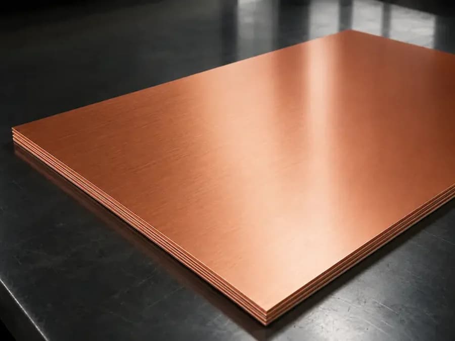
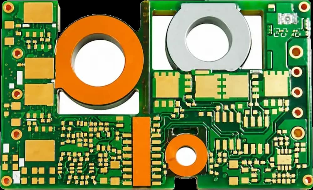
HyperPCB manufactures aluminium and copper core PCBs with thermal conductivity from 1.0 to 6.0 W/mK for LED lighting, power conversion and motor drives, in single-sided, double-sided and hybrid constructions.
— SPECIFICATIONS
Capability & tolerance chart
| Parameter | Standard | Advanced |
|---|---|---|
| Supported Structures | Single-sided metal core, double-sided metal core with plated through holes, multilayer and hybrid metal-backed builds | — |
| Core and Base Materials | Aluminium core, copper core and direct thermal path copper structures | — |
| Finished Board Thickness | 39.4 – 197 mil | — |
| Thermally Conductive Dielectric | 0.5 – 8.0 W/m·K, subject to material selection | — |
| Registration Accuracy | 1.97 mil single-sided | 2.95 mil double-sided / PTH |
| Routing / Forming Accuracy | ±3.94 mil | — |
| Profile / Positional Tolerance | ±7.87 mil | ±5.91 mil on advanced builds |
| Back-Drill Depth Tolerance | ±7.87 mil where applicable | ±3.94 mil where applicable |
| Surface Finishes | Lead-free HASL, ENIG, electrolytic gold, immersion tin, OSP | — |
| Production Support | Prototype, low-volume and volume production | — |
Thermal resistance, not just conductivity
The number that matters to your junction temperature is the thermal resistance from component pad to heatsink, and the dielectric layer dominates it. A 6 W/mK dielectric at 100 µm behaves very differently from 1 W/mK at the same thickness, so we quote the combination rather than a single headline figure.
Machining and isolation
Metal core boards are routed, counterbored and tapped as metal parts, and the exposed core must stay electrically isolated from the circuit. Mounting holes, clearances and edge isolation are reviewed with your mechanical drawing before tooling.
— FAQ
Frequently asked questions
— RELATED
Related capabilities
Ready to build?
Upload your Gerber files for a free DFM review and a quote within 24 hours. Mutual NDA available.