— CAPABILITIES
High-Frequency PCB Capability
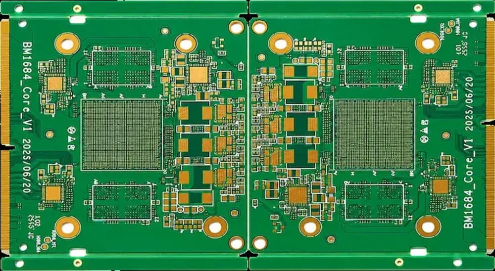
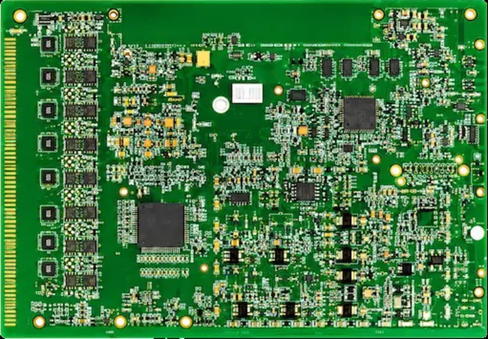
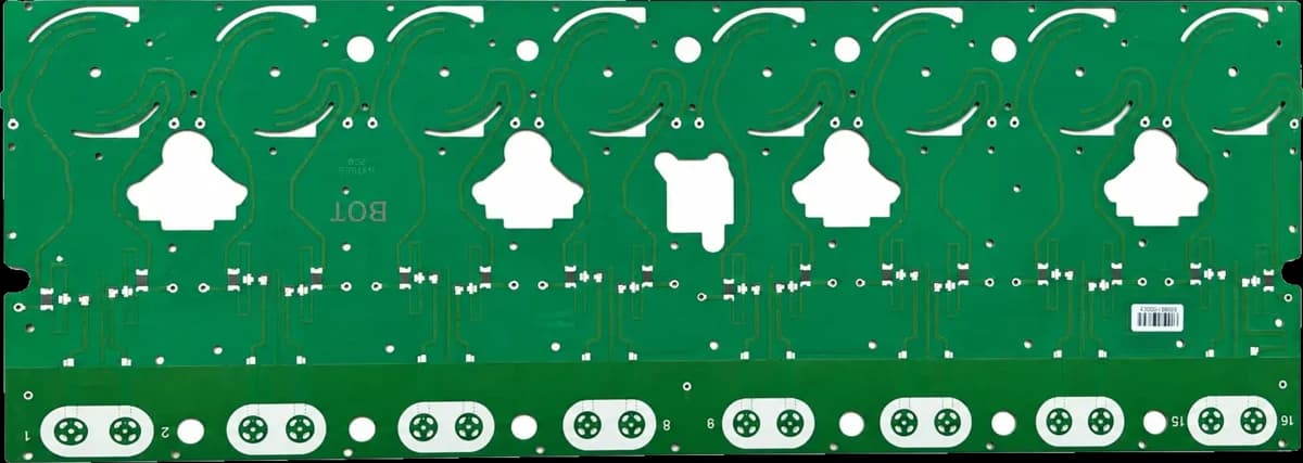
HyperPCB fabricates high-frequency PCBs on laminates it manufactures itself, covering Dk 2.17 to 10.2 with PTFE, hydrocarbon-ceramic and composite substrates, signal integrity verified to 40 GHz and impedance held to ±7%.

— SPECIFICATIONS
Capability & tolerance chart
| Parameter | Standard | Advanced |
|---|---|---|
| PCB Types | High-frequency, RF, microwave, antenna, mixed dielectric and high-speed high-frequency boards | — |
| Material Types | PTFE, ceramic-filled PTFE, hydrocarbon ceramic-filled, PPO/PPE, modified epoxy, low-loss and high-speed systems | — |
| Layer Count | 2-layer to multilayer | High-layer mixed dielectric structures by project review |
| Board Thickness | 5 – 197 mil, depending on material and stack-up | — |
| Maximum Board Size | 570 × 500 mm for high-frequency precision work | Larger sizes depending on material and structure |
| Minimum Line Width / Spacing | 2.5/2.5 mil standard process | 1.38/1.38 mil for advanced products, design-dependent |
| Line Width Tolerance | ±0.59 mil for precision microwave lines | — |
| Minimum Mechanical Drill | 3.94 mil for advanced structures | — |
| Controlled Impedance | ±8% typical | Tighter tolerance by project review |
| High-Speed Signal Support | Up to 128 Gbps class by stack-up and material review | — |
| Special Processes | Back drilling, controlled-depth routing, step grooves, blind and buried vias, resin-plugged vias, metal edge plating, mixed dielectric lamination | — |
| Surface Finishes | ENIG, ENEPIG, OSP, immersion silver, immersion tin, hard gold, soft gold | — |
The laminate is the product
Above a few gigahertz the board stops being a wiring medium and becomes part of the circuit. Because we fabricate the laminate, dielectric constant, loss tangent, resin content and copper profile are known and repeatable across batches — no substitution notice halfway through your production run.
Hybrid stack-ups
Most RF products only need low-loss material on two or three layers. Bonding PTFE or hydrocarbon-ceramic layers to FR-4 cores keeps the RF performance where it matters and the cost where it belongs. We model the hybrid stack-up and confirm the bond system before quoting.
What we need to model your line
Target impedance and tolerance, operating frequency, the reference layer for each controlled line, and whether loss or phase stability drives the design. We return the stack-up with modelled trace widths and the measured Dk we will build to.
— FAQ
Frequently asked questions
— RELATED
Related capabilities
Ready to build?
Upload your Gerber files for a free DFM review and a quote within 24 hours. Mutual NDA available.