— CAPABILITIES
High-Speed PCB Capability
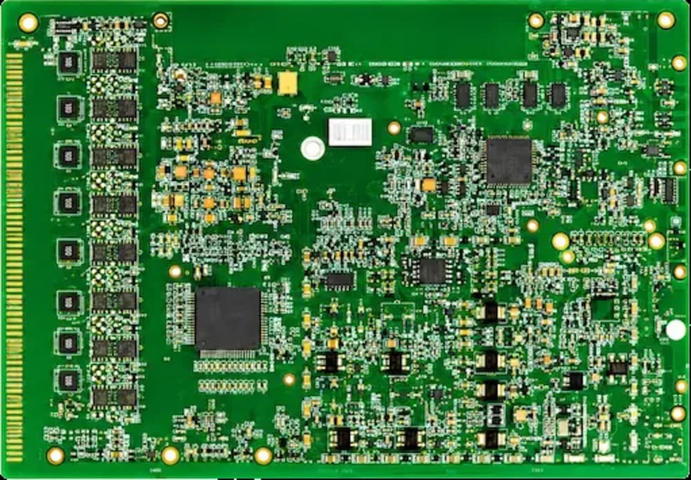
HyperPCB manufactures high-speed digital PCBs with ±7% controlled impedance, low-loss and hybrid stack-ups, back-drilled stubs and TDR verification on every controlled-impedance lot — up to 48 layers with 50 µm laser vias.
— SPECIFICATIONS
Capability & tolerance chart
| Parameter | Standard | Advanced |
|---|---|---|
| PCB Types | High-speed, controlled-impedance, high-layer-count, server, networking and optical module boards | — |
| Layer Count | 4 – 48 layers | — |
| Maximum Board Size | 1000 × 600 mm for high-layer-count builds | — |
| Finished Board Thickness | 11.8 – 276 mil for high-layer-count boards | Thicker structures by project review |
| Minimum Line Width / Spacing | 1.97/1.97 mil | 1.38/1.38 mil for advanced high-density products |
| Line Width Tolerance | ±0.59 mil for precision signal structures | — |
| Minimum Mechanical Drill | 3.94 – 5.91 mil, depending on structure | — |
| Through-Hole Aspect Ratio | Up to 20:1 | — |
| Controlled Impedance | ±10% | ±7% by stack-up, material and design review |
| High-Speed Signal Support | Up to 128 Gbps class by stack-up and material review | — |
| Back Drilling | Supported for stub reduction in high-speed channels | — |
| Via Structures | Through, blind, buried, via-in-pad, resin-plugged, filled and capped vias | — |
| Advanced Processes | Back drilling, sequential lamination, controlled-depth routing, step grooves, edge plating, embedded copper | — |
| Materials | Low-loss, high-speed, High Tg FR-4, halogen-free FR-4 and mixed dielectric systems | — |
Impedance is a manufacturing outcome
A trace width that models correctly still fails if etch, dielectric thickness and copper roughness are unknown. We work backwards from your target: choose the dielectric we fabricate, compensate the artwork for etch, then measure the result by TDR on coupons from the same panel as your boards.
Via stubs and back drilling
At multi-gigabit rates an unused via stub is a resonator. Where the layer transition allows, back drilling removes the stub to 0.20 mm as standard and 0.15 mm on request, with depth verified on cross-sections.
— FAQ
Frequently asked questions
— RELATED
Related capabilities

Ready to build?
Upload your Gerber files for a free DFM review and a quote within 24 hours. Mutual NDA available.