— CAPABILITIES
Rigid-Flex PCB Capability
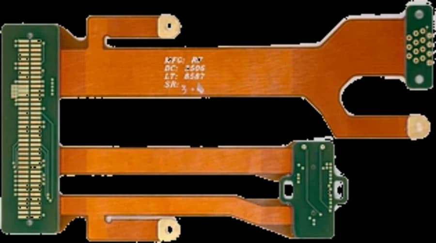
HyperPCB builds rigid-flex PCBs that replace connectors and cable harnesses with one laminated assembly — polyimide flex layers bonded into rigid sections, with controlled impedance, coverlay or solder-mask finishing and stack-up review included.
— SPECIFICATIONS
Capability & tolerance chart
| Parameter | Standard | Advanced |
|---|---|---|
| PCB Type | Rigid-flex, multilayer rigid-flex, HDI rigid-flex | — |
| Layer Count | 2 – 24 layers | Up to 32 layers for advanced projects |
| Maximum Finished Size | 700 × 480 mm | — |
| Finished Board Thickness | 11.8 – 197 mil, depending on structure | — |
| Minimum Flexible Layer Width | 59.1 mil | — |
| Minimum Inner Layer Line Width / Spacing | 1.97/1.97 mil | — |
| Minimum Outer Layer Line Width / Spacing | 2.46/2.46 mil for advanced projects | — |
| Minimum Through Hole | 5.91 mil | — |
| Minimum Blind Via | 2.95 mil | — |
| Through-Hole Aspect Ratio | Up to 20:1 | — |
| Blind Via Aspect Ratio | Up to 1:1 | — |
| Maximum Finished Copper | Up to 3 oz | — |
| HDI Structures | 2+N+2, 3+N+3 | Any-layer HDI by project review |
| Flexible Materials | Polyimide-based flexible laminates | — |
| Special Processes | Coverlay, stiffener bonding, selective plating, controlled-depth routing, laser cutting, impedance control | — |
The transition zone decides reliability
Rigid-flex failures cluster where the flex leaves the rigid section. We keep copper out of the bend, stagger traces on opposing layers, round every corner and set the coverlay opening back from the rigid edge. If your outline forces a tight bend we will show you the trade-off in the DFM review rather than build it quietly.
Dynamic versus static bends
A board that folds once during assembly and a board that flexes a million times in service are different products. Tell us the cycle count and bend radius and the build changes accordingly: rolled annealed copper, thinner dielectrics, single-layer flex in the bend and no plated holes inside the bend area.
Documentation you should send
A mechanical drawing showing bend lines, bend direction and the folded envelope matters as much as the Gerbers. Stiffener locations, coverlay openings and the assembly sequence let us confirm the part fits before tooling.
— FAQ
Frequently asked questions
— RELATED
Related capabilities
Ready to build?
Upload your Gerber files for a free DFM review and a quote within 24 hours. Mutual NDA available.