— SOLUTIONS
Rigid-Flex PCB Solutions
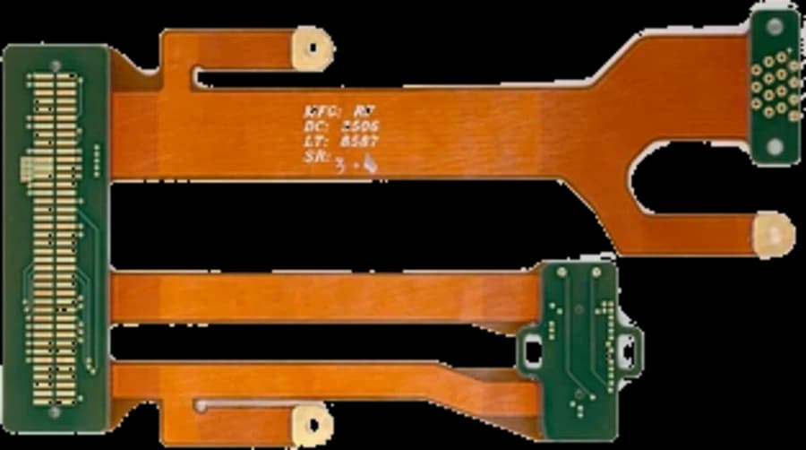
HyperPCB delivers rigid-flex PCB solutions that remove connectors and cable harnesses from an assembly — up to 6 flex layers inside a 20-layer stack, with bend-radius review, controlled impedance and stiffener options included.
— SPECIFICATIONS
Capability & tolerance chart
| Parameter | Standard | Advanced |
|---|---|---|
| Bend Radius | 3 – 6× flex thickness for static installation bends | 10 – 20× plus 50% margin for dynamic flexing |
| Flex Materials | Adhesive-based acceptable for static bends | Adhesiveless required for dynamic flexing |
| Trace Placement | Preferred on the neutral axis | Neutral axis mandatory for dynamic flexing |
| Flex Life | 10 – 100 cycles on installation bends | Bend-cycle tested for service flexing |
| Coverlay | Recommended where abrasion is a risk | — |
| Layer Count | 2 – 24 layers | Up to 32 layers on advanced projects |
| Maximum Finished Size | 700 × 480 mm | — |
Fewer interconnects, fewer failures
Each connector and cable in an assembly is a mechanical joint that can fatigue, corrode or be assembled incorrectly. Folding those interconnects into the board removes the joints entirely, which is why rigid-flex tends to win on reliability before it wins on space.
Design review before tooling
We review bend lines, copper placement in the bend, coverlay set-back, stiffener positions and the folded envelope against your mechanical drawing, and report findings in writing before the first panel is cut.
— FAQ
Frequently asked questions
— RELATED
Related solutions
Ready to build?
Upload your Gerber files for a free DFM review and a quote within 24 hours. Mutual NDA available.